Finding vulnerabilities, hacks, exploits, and full root access are goals for security engineers when they begin to assess a device, right? But when working with hardware, you cannot simply dive into the hacking on day one. Your exploits will only be as successful as the setup work you’ve done!
This post will discuss the process of instrumenting an automotive module for bench testing. Bench testing is a technique in which an engineer runs an automotive module outside of a vehicle, on their work bench, with all of its various harnesses pinned out and available for connection. A bench testing environment allows us to conduct a more scientifically rigorous engagement. This is because a production automobile’s many modules, networks, and even physical limitations introduce multiple variables to the testing environment. A test bench allows an engineer to connect to various interfaces on the module, power cycle it as needed, and isolate the module from extraneous variables.
Instrumentation involves three main phases–recon, hardware setup, and testing. We will be walking through each one to provide an in-depth look at the start of every hardware engagement at Praetorian!
In our example setup, we’re going to treat this module as a total black box. This means that we have no documentation on our unit, an older Subaru head unit (see Figure 1). We know nothing about it, and have never interfaced with it before. We did not choose this unit for any particular reason other than its being free on Facebook Marketplace! Everyone knows that free things are the best things to reverse engineer, because you don’t have to worry about breaking them. We hope to demonstrate that the test bench setup process is applicable to any automotive module, even the freebies.

Figure 1: The module that we will be instrumenting, an older Subaru head unit.
Reconnaissance
To instrument a module, we must be aware of all of the device’s connectors and their pinouts. Whether a connector’s purpose is to power the device or to connect to the module’s CAN interface, this is one of the most important pieces of information to learn about a module. Before pulling out the multimeter, I always turn to Google in search of wiring diagrams and pinouts. Figure 2 shows our module’s plethora of connectors.
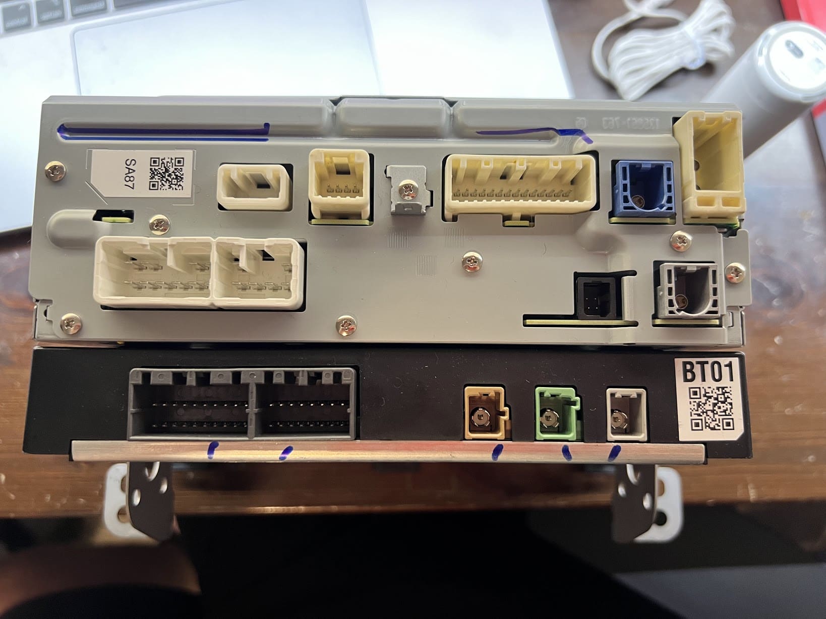
Figure 2: The rear of the module, showing a multitude of connectors and pins!
To locate more documentation on the module, we need to know the following things about it:
- The module’s part number
- The donor vehicle’s make
- The donor vehicle’s model
- The donor vehicle’s model year
Using this information, we should be able to locate repair manuals, documentation from the manufacturer, and potentially even public reverse engineering efforts.
Lucky for us, we already have two pieces of information out of the way: the make and model of the vehicle it came from. When acquired, this module was listed as a “Subaru Legacy radio.” While we do not know the model year yet, this is a great starting point. To continue our hunt for documentation, we will look for the part number next.
Part Number
To find the part number, we will look for any large label on the module. Almost all automotive modules have stickers, labels, or engravings on them stating their part number, as almost every part of a vehicle is built with replacement, repair, or diagnostics in mind. This makes finding automotive module documentation far easier than when attempting the same for traditional consumer electronics.
Figure 3 shows our module’s label.
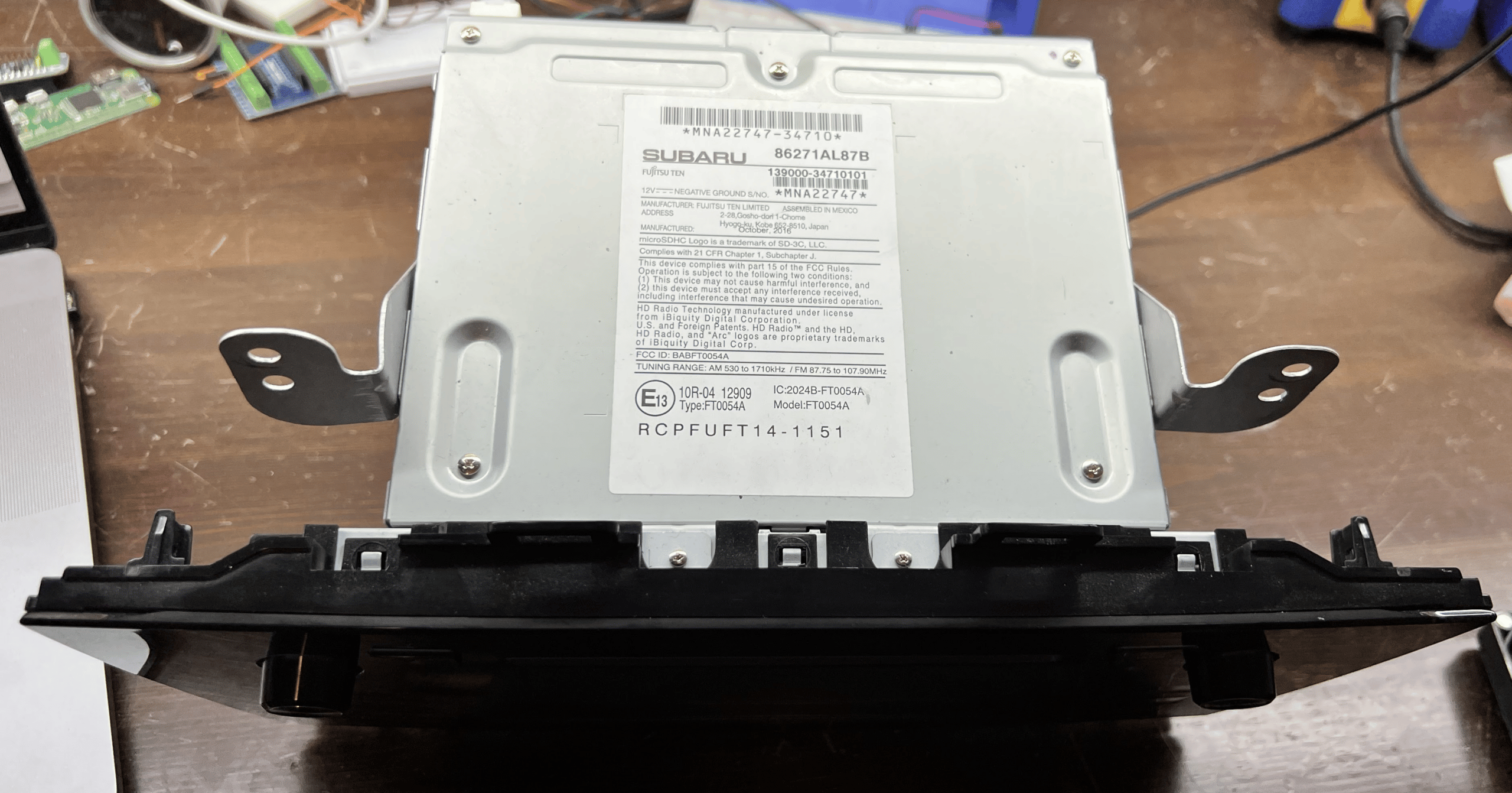
Figure 3: The label on our Subaru head unit.
In this case, we have more than a few numbers on our label, which can feel overwhelming! Let’s take a closer look at the ones in Figure 4.
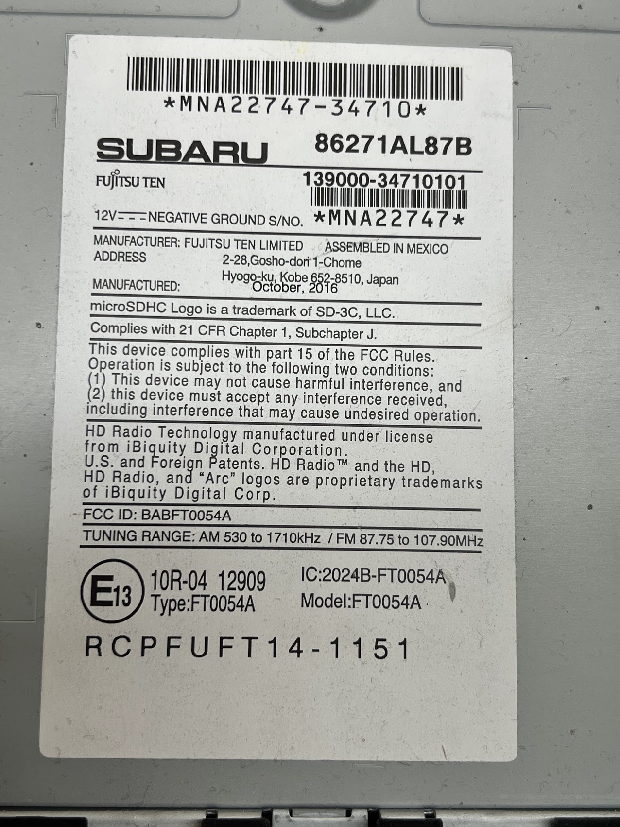
Figure 4: A portion of our module’s label with the information relevant to our purposes.
Subaru – This one should be obvious, our radio is from a Subaru!
Fujitsu Ten – This radio is built by Fujitsu Ten and merely integrated into the vehicle by Subaru. Many times, if you see a logo on an automotive part that is not the automaker’s, it will be the logo of the automotive supplier that developed the part.
86271AL87B – This is most likely the part number. When in doubt, do a Google search of the number written in the largest font!
139000-34610101, MNA22747 – While currently unknown to us, these barcodes are commonly included to allow a manufacturer to find the exact date a device was produced, which assembly plant produced it, and possibly the batch or revision of the device. While not usually helpful to the reverse engineering process, these numbers may be helpful in the future if we discover an exploit that only works on a specific revision of a module. In that case, we will need this information to help determine when and where the affected module was produced.
Vehicle Model and Year
Now that we have numbers with which to work, we will start by performing a Google search of the number written in the largest font– “86271AL87B “. The search confirms that this number is in fact the part number, bringing up multiple results on parts.subaru.com , the Subaru parts website. According to the Subaru Parts website, that part number is for a Radio and Navigation Unit (that sounds like what we’re looking for) that was installed in the 2017 Subaru Legacy and Outback. This is a big help. Now that we have the exact year and model of the vehicle our module is from, we can begin to look for connectors or harnesses to get this module up-and-running on a bench for further research!
Wiring Harnesses and Connector Pin-Outs
To find more information or documentation about a part, such as wiring harnesses, connector pin-outs, or other useful information, we will have to dig a bit deeper online. In addition to searching the part number alone, another useful technique for finding product documentation is to search the part number with “PDF” at the end. Searching “86271AL87B PDF ” led to me finding this wonderful document , entitled “Technical Support Guide – Micro SD Navigation (AVN) Display Audio (DA)” on the National Highway Traffic Safety Administration (NHTSA) website! This document has much of the information we will need to complete our bench setup and begin reverse engineering, including pinouts and a user manual.
Now, to answer a side question: Why in the world would the NHTSA website host a Subaru service manual document and wiring diagrams? The NHTSA offers a resource that consumers can access in order to learn about potential vehicle recalls, issues, complaints, and crash safety information. In many cases, automakers will upload supporting documents to a recall or Technical Service Bulletin (TSB). Doing so gives the consumer or repair facility further knowledge on the source of an issue, instructions on how an issue can be remedied, or other repair-related documentation. This is the service to which Subaru’s engineers uploaded our Subaru service manual, most likely as part of a TSB.
From here, we seem to be ready for take off. We have the following information:
- The name, year, and model of the vehicle in which the module was installed
- Information on the manufacturer of the module, for further Googling
- A technical support guide PDF that details block diagrams of the radio’s connectivity, pinouts of all of the connectors, and more
We’re all ready to start setting up the device for bench testing.
Powering Up
The most basic step of instrumentation is power! Before all else, most automotive modules will require ~12V DC (the usual voltage supplied by a car battery) to power on. To identify which connector and pins can be used to supply the module power, we just have to check our NHTSA PDF file. Figure 5 shows a diagram we found on page 24.
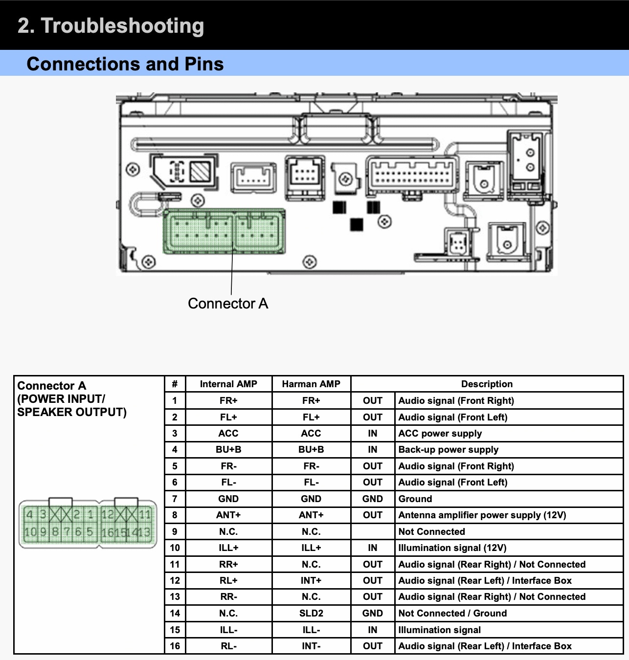
Figure 5: A diagram showing how to pin out this module. We can supply power to the module by sending 12V to pin 3 and connecting our ground to pin 7.
Additionally, we found the diagram in Figure 6 one page later.
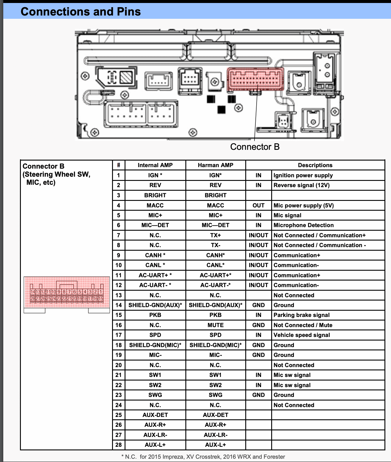
Figure 6: A supplementary diagram that shows an Ignition Power Supply wire, which we also will need to connect to 12V.
Connectors and Harnesses
From our two power supply diagrams we understand what we need to do, so all that remains is to connect to these pins. In an engagement where the client supplies the module under test, we ask the client to provide the connectors and wiring harness with the module. Using official connectors and harnesses to pin out to your tools is truly the best route.
That being said, security research often takes place on modules extracted from crashed vehicles, purchased off eBay, etc. In that case, you need to find a way to connect to the module without any manufacturer support available! Options for sourcing your materials include the following:
- Visit your local junk yard! Many junk yards will let you purchase connectors or even entire harnesses for pennies on the dollar when compared with buying them new. Some manufacturers also use the same connectors in multiple years or models, so you may not need your vehicle year’s harness in particular!
- Check the manufacturer’s website. Subaru themselves may sell the harness, in the case of this module.
- Search eBay. Perhaps someone has cut the harness you need out of a crashed vehicle and has it available for sale online.
- DIY! If harnesses are completely unavailable or time is of the essence, you will need to connect to the pins in any way possible. This could be with jumper wires, “mini grabber” IC test clips, or soldering wires directly to the pins or PCBs of the device.
While we always recommend engineers use a fully pinned-out harness when possible, option four is a viable early option during an engagement, particularly if you cannot get a harness quickly! This was the issue I ran into, for the following reasons:
- No local junk yards had any Subaru vehicles past 2010.
- The Subaru website seemed to have a number of connectors, but I wasn’t ready to spend over $200 on a harness
- eBay was a no-go.I found many Radio Harnesses meant to adapt the Subaru harness to an aftermarket radio, but no one was selling the male side of the harness that comes from the vehicle.
Because of this, I decided to start without any harness.
Wiring Yourself Into Automotive Connectors
First things first, we should look at the physical pins that we are looking to connect our tools to, which we can see in Figure 7:

Figure 7: The pins to which we need to connect our tools.
On Connector A, we have a number of spade/blade-style connectors. These can be problematic due to their shape, as normal, round jumper wires meant to connect to traditional pins will not work here!
On Connector B, we have standardized jumper-sized round pins. A simple female jumper cable should work!
So, we will focus our attention on Connector A. The name of the game here is space. Figures 8-10 show three easy ways to connect to spade-style pins in the absence of the original connector:
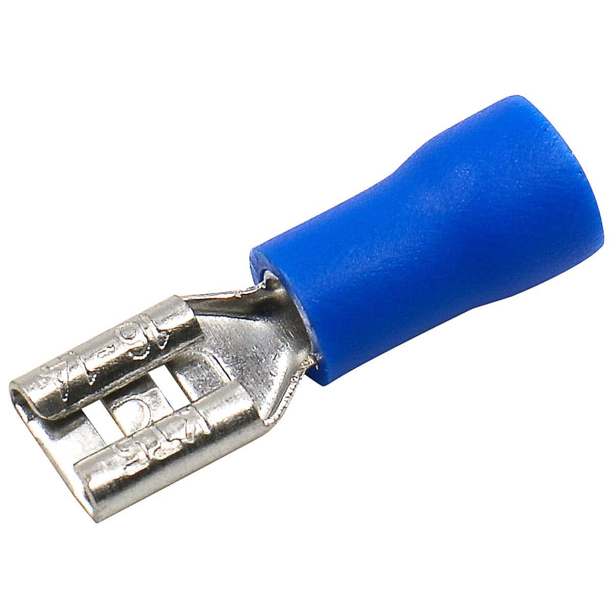
Figure 8: A spade-style jumper. You can measure the spade pin using calipers to get its exact dimensions, and then order spade jumpers of the correct size online.
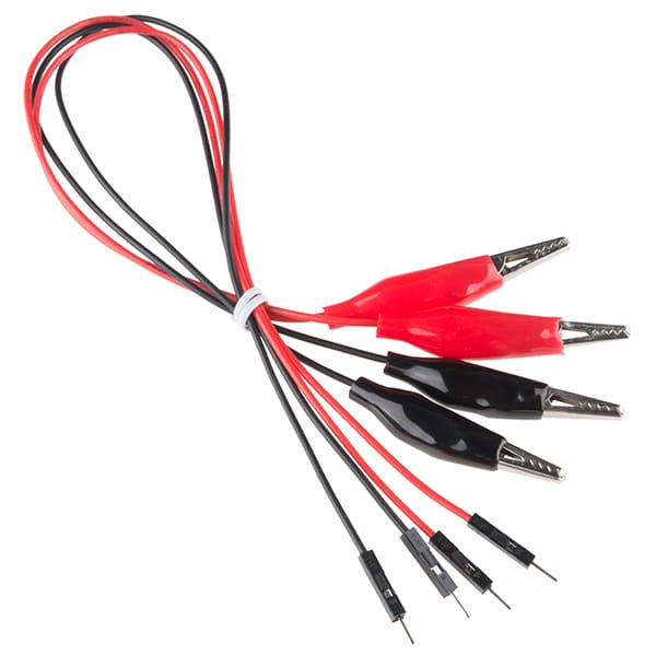
Figure 9: Alligator clips. If you have enough room within the connector, and the spade pins are large enough, alligator clips will work well! These are an easy and quick solution, but are prone to falling off when bumped.
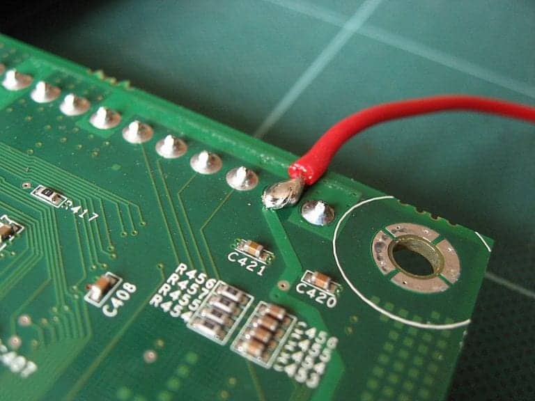
Figure 10: Solder. This is a last resort, but you can technically solder wires directly onto the exposed pins, or on the PCB where the pins connect to the board. Soldering is never my first choice, as doing so creates more work to reverse or disassemble.
Out of the available options, I’m going with number two. I explored ordering spade connectors for option one, but the 2.3mm spade connectors would have taken two to three weeks to ship. With alligator clips on-hand, the world was my oyster.
Connecting the Power and Ground
From here, we can connect to the pins. According to our diagrams, our important pins were as follows:
| Connector A – Pin 3 | 12V (ACC Power Supply) |
| Connector A – Pin 7 | Ground (GND) |
| Connector B – Pin 1 | 12V (IGN – Ignition Power Supply) |
| Connector B – Pin 23 | Ground (GND) |
We see in Figure 11 how they connect.
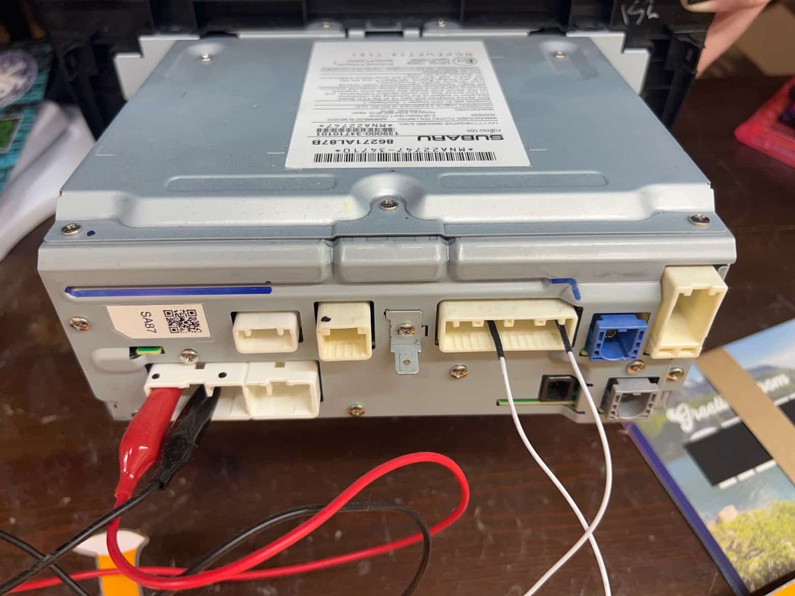
Figure 11: Our module connected for power and ground.
Due to multiple connectors requiring power and ground, I attached each to a banana plug breakout board and stacked for ease of access and modularity, as Figure 12 shows. I then connected these banana plugs to the bench-top power supply which provides the 12V DC power.
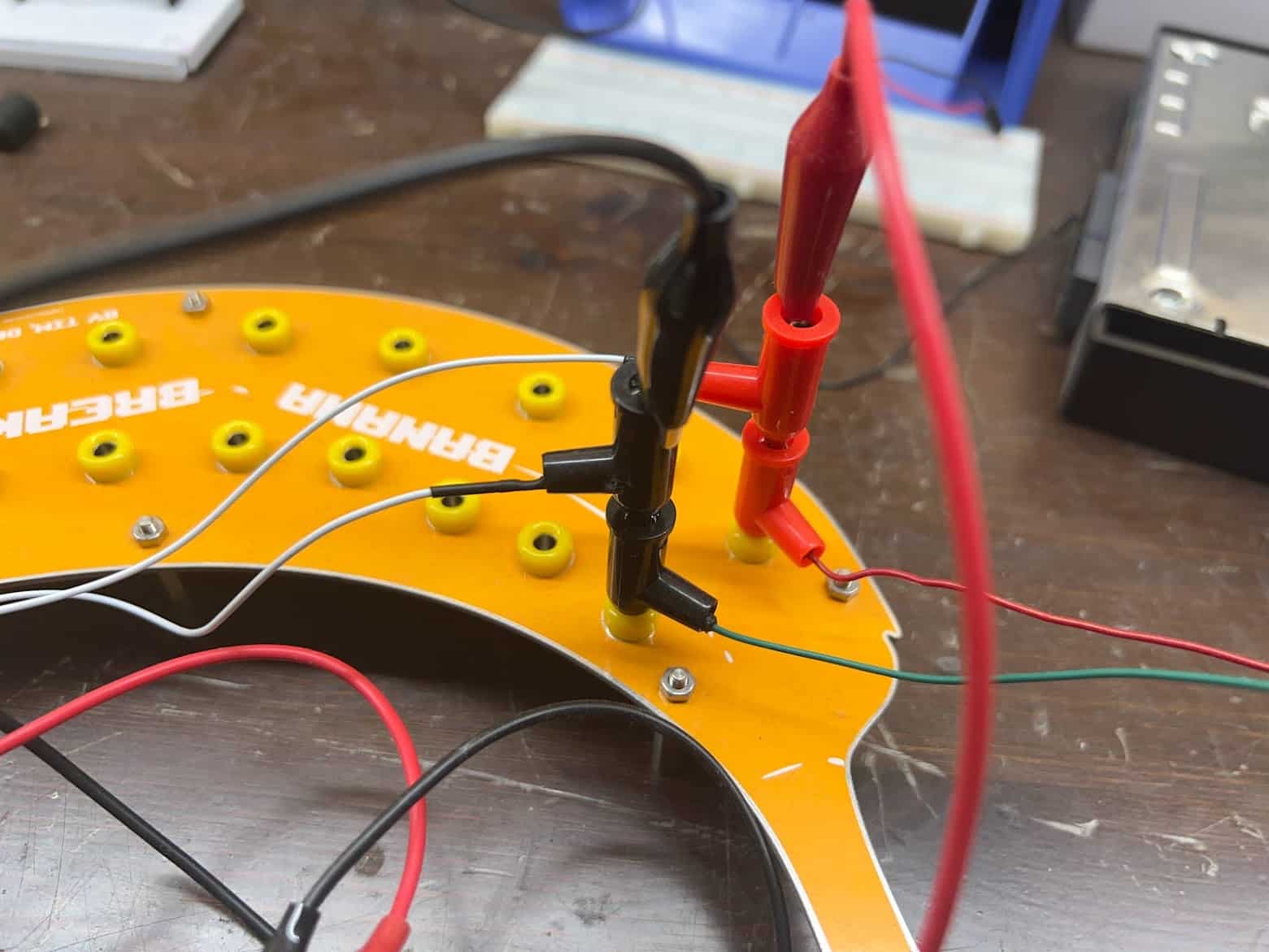
Figure 12: Power and ground connectors stacked on a banana plug breakout board.
With all of our power-related pins now connected, we should be ready to boot! A bench-top DC power supply will deliver power at 12V. Once we turn it on, you can see in Figure 13 that our head unit successfully boots!
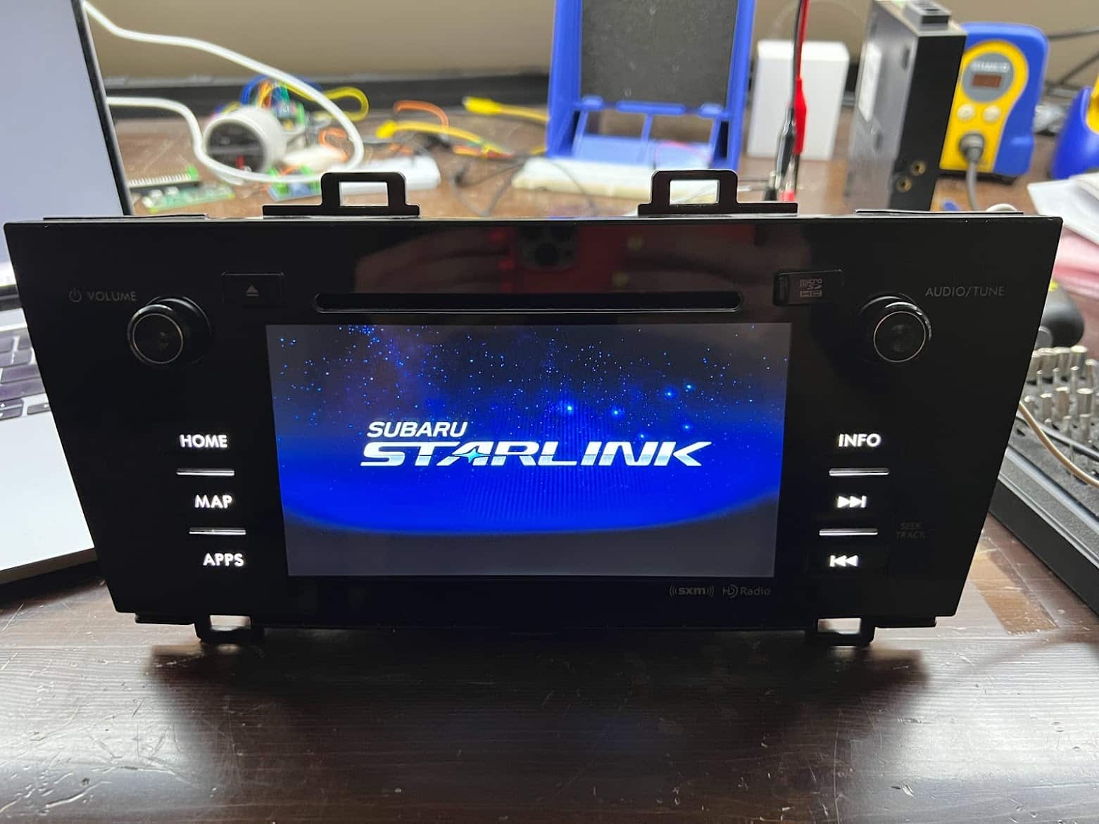
Figure 13: Our module successfully powered on.
From here, the actual security assessment work can begin. You can pin out the head unit’s CAN bus, disassemble the unit further to attach to debug ports, and more.
Connecting to CAN
As a quick demonstration of the ease of access provided by our new bench-top setup, we will connect to this head unit’s CAN bus pins. For our CAN transceiver, I’ll be using an PEAK PCAN-USB adapter connected to a laptop running Ubuntu Linux. When combined with the socketcan suite of utilities provided on Linux, this should provide all of the functionality we need for capturing and transmitting data over the CAN bus.
Per our diagrams in figures 5 and 6, we see that our “CAN High” and “CAN Low” pins reside on pins 9 and 10 of Connector B. This was the connector that was perfect for connecting to with two basic jumper wires! Figure 14 shows the CAN High and CAN Low pins connected to our USB to CAN adapter, which we then plugged into our testing laptop.
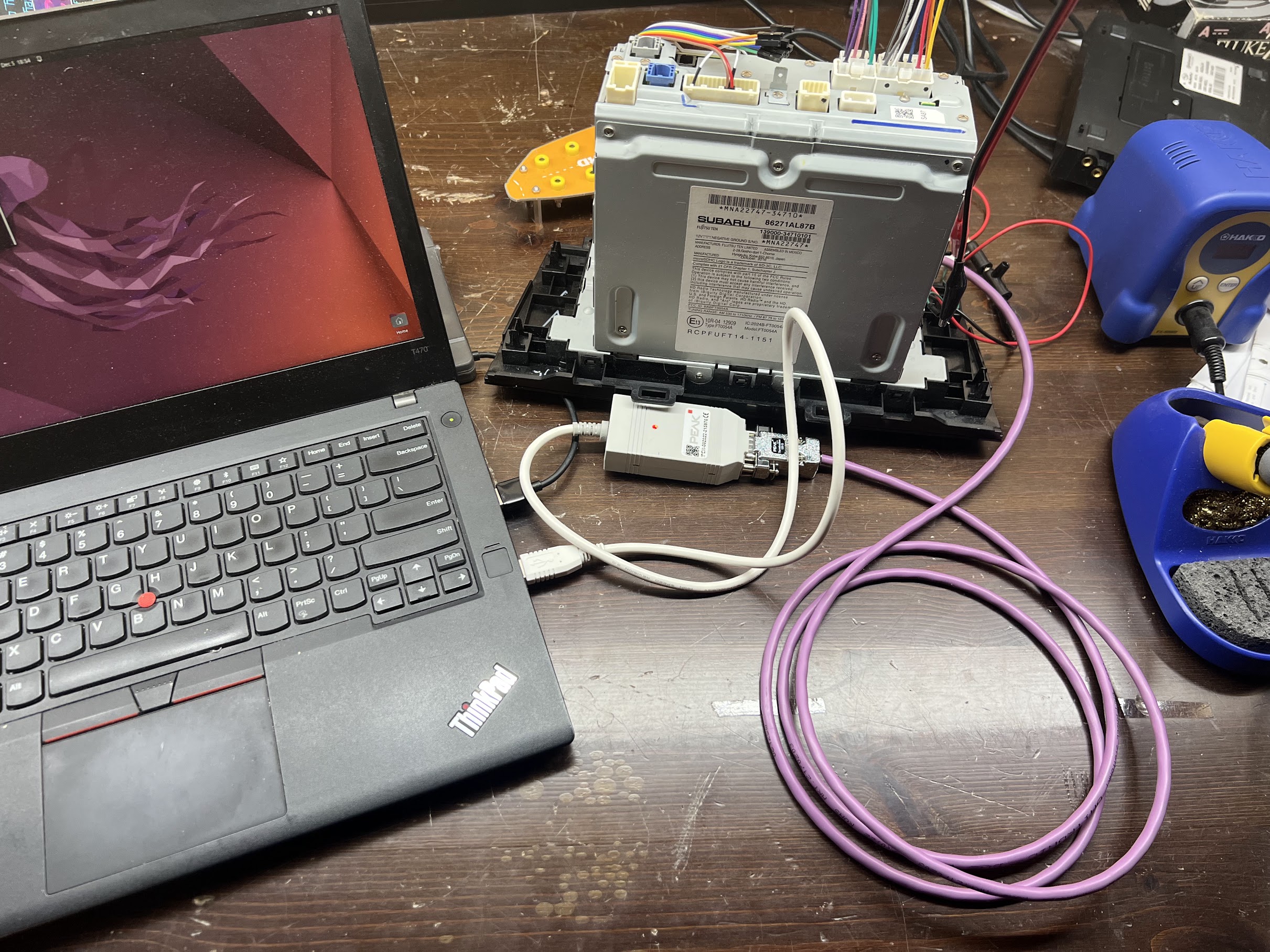
Figure 14: Jumper wires connecting CAN adapter and module.
Determine Bitrate
Before we can bring up our CAN adapter on Linux, we will have to do a tiny bit more research to determine the vehicle’s CAN bitrate. Unfortunately, this is not a value that our NHTSA document listed. While it most likely resides in another piece of Subaru-supplied documentation, I decided simply to try each of the most common bitrates until one worked. The top three most common bitrates are 500,000, 250,000, and 125,000. While other bitrates may be in use, iterating through a list of common CAN bitrates often is faster than searching for documentation that lists this value.
Initialize and Collect Data
From here, we will simply initialize our USB to CAN adapter on Ubuntu using the `ip` utility, as shown in Figure 15.
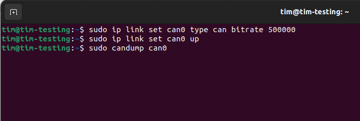
Figure 15: Screenshot showing sudo ip link set can-up, with bitrate.
And then we can begin dumping the data being transmitted on the bus using the `candump` utility, as Figure 16 shows:
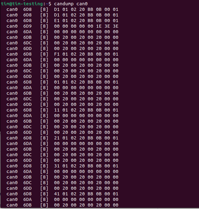
Figure 16: Screenshot showing candump can0.
Conclusion
We have reverse engineered, powered on, and instrumented a previously-unknown Subaru head unit. We are now able to intercept the module’s CAN traffic, broadcast malicious CAN data to the unit, or interact with the device’s running software. At this point, the world is our oyster for doing live and interactive attacks with the unit.
My previous blog post, The Anatomy of an Automotive Security Assessment , provides further insight on Praetorian’s automotive security assessment process. If you have any questions regarding instrumenting your own unit, would like more insight into the automotive security testing process of Praetorian, or would just like to chat, feel free to send an email! My email address is [email protected], and I’m always happy to talk.
Happy hacking!